MMIX Stopwatch Example

Content
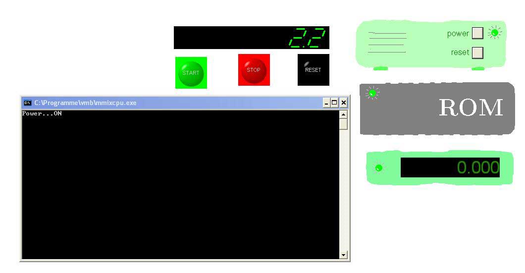
Besides a MMIX CPU, it features a small ROM containing the software, a millisecond timer, a sevensegment display, and three buttons for START, STOP, and RESET. The configuration is described in the file default.vmb.
It illustrated interrupt handling with MMIX in a very simple setting. Since the whole program runs in negative addresses, there is no switching between user mode and operating system mode. Further, there is no need for forced TRAPs, since there is no user program anyway.
Running
To run the example, you need the configuration file default.vmb and the ROM image bios.img as well as the usual vmb software package from the VMB Homepage (minimum software requirement: button, sevensegment, timer, rom, mother and mmixcpu). To start the Stopwatch, just double click on the default.vmb File and then click the power button on the motherboard.Pressing the green START button starts the stopwatch and pressing the red STOP button stops it. The display can be reset to zero by pressing the black RESET button.
Building the Software
To build the software you will nedd the mmix assembler and a converter from object files to ROM images.From the bios.mms source file, the bios.mmo object file is created using the mmix assembler like this: mmixal bios.mms
The ROM Image File bios.img is then created from the object file
bios.mmo using
mmoimg with the command
mmoimg bios.mmo
Modifying the Software
To modify the software, edit the source file bios.mms and repeat the build process.To undestand the source code better, some remarks may be helpful.
- The Code starts with the boot sequence, establishing some reasonable values for special registers.
- Strictly needed is the value in rTT, which must point to the entry point for dynamic interrupts.
- A global register is allocated as a counter by setting the rG register.
- The boot sequence ends in an infinite loop waiting for interrupts. Before entering the loop, the interrupt mask register rK must be set to enable the expected interrupts. All interrupts can be enabled at that point except for the Privileged Interrupt. This interrupt must not be enabled while running at negative (privileged) addresses.
- The START and STOP button interrupts enable or disable the timer.
- The RESET button resets a global register count to zero and displays the new value.
- The timer interrupt increments the count register and displays the new value.
- The final subroutine displays the value of the count register in the sevensegemnt display. Each digit in the display corresponds to one byte; and each segment corresponds to one bit of the byte. The counter value is converted to decimal and encoded digit by digit. Finally, the bit pattern is written to the sevensegment display.